Developer Information
Table of Contents
1. Benchmarking (toc)
NAND
| Way | 1 Page Read (32KB) - 2 Plane | |
|---|---|---|
| 1 Channel | 2 Channel | |
| 1 Way | 39.29 MB/s | 78.58 MB/s |
| 2 Way | 51.42 MB/s | 102.60 MB/s |
| 3 Way | 49.63 MB/s | 99.05 MB/s |
| 4 Way | 51.45 MB/s | 102.78 MB/s |
MMU
| mem_set_dram | 302.88 MB/s |
SATA
| READ | 260 MB/s |
| WRITE | 260 MB/s |
SATA performance is measured using ftl_dummy.
ftl_dummy is a special firmware used to benchmark the raw throuput of the Barefoot controller and DRAM, no NAND operations are performed. On an ICH10 South Bridge the Jasmine board should reach approximately 260MB/sec on both read/write operations. If you’re not getting those numbers here are some tips:
- Make sure the controller is in AHCI mode and the Jasmine board was initialized when the OS loaded (ie: not hot swapped)
- Benchmark on a clean installation of Windows with no programs (eg: Antivirus) installed.
- Benchmark sequential reads in Linux using a bootable CD (e.g. SysRescueCD) with a 4KB block size.
$ ddrescue –-block-size=4096 /dev/sda /dev/null
2. Hardware (toc)
MMU
When interacting with DRAM use the MMU functions in ‘mem_util.c’. Direct DRAM access from the CPU bypasses the ECC engine and requires additional address translation or arbitrary data will be returned. Direct reads are discouraged because ECC errors will not be corrected. Direct writes should be avoided as ECC information will not be updated and future ECC reads would interpret the updated information as erroneous.
If the DRAM ECC engine is disabled NAND <-> DRAM operations will only work on channels A and B (not C and D).
Timers
The Barefoot controller has four countdown timer channels which can be programed with three different resolutions. Timer channel 4 is reserved for the retry timer and should not be used.
Timer Resolution
| FLAG | Input Clock divided by | Resolution | Ticks/sec | Maximum Precision |
|---|---|---|---|---|
| TIMER_PRESCALE_0 | 1 | 11.32ns per tick | 87,489,064 | 49s |
| TIMER_PRESCALE_1 | 16 | 182ns per tick | 5,494,506 | 781s |
| TIMER_PRESCALE_2 | 256 | 2.9us per tick | 344,828 | 12,455s |
Programming the Timer
start_interval_measurement(TIMER_CH1, TIMER_PRESCALE_0);// Program TIMER_CH1 to coundown from 0xFFFFFFFF
							// Using TIMER_PRESCALE_0 11.43ns per tick

UINT32 ticks = (0xFFFFFFFF - GET_TIMER_VALUE(TIMER_CH1));// Retrieve the number of ticks since programming
Timer Interrupts
The TM_INTR flag must be sent to SET_TIMER_CONTROL to tell the timer to generate an interrupt and INTR_TIMER_x must be enabled in APB_INT_MSK to allow the interrupt controller send an interrupt to the ISR, which is done by default in the initialization code.
SETREG(APB_INT_MSK, INTR_SATA | INTR_FLASH | INTR_SDRAM | INTR_TIMER_1 | INTR_TIMER_2 | INTR_TIMER_3);
Programming the timer to send interrupts
SET_TIMER_CONTROL(TIMER_CH1, 0);
CLEAR_TIMER_INTR(TIMER_CH1);
SET_TIMER_LOAD(TIMER_CH1, 87489064);	// Countdown from 1 second
SET_TIMER_CONTROL(TIMER_CH1, TM_ENABLE | TM_BIT_32 | TM_INTR | TM_MODE_PRD | TIMER_PRESCALE_0);
while(1);
irq_handler() in misc.c
if (intr_stat & (INTR_TIMER_1 | INTR_TIMER_2 | INTR_TIMER_3))
{
	CLEAR_TIMER_INTR(TIMER_CH1);	// Clear Timer Interrupt
	CLEAR_TIMER_INTR(TIMER_CH2);
	CLEAR_TIMER_INTR(TIMER_CH3);
	SETREG(APB_INT_STS, INTR_TIMER_1 | INTR_TIMER_2 | INTR_TIMER_3);  // Clear Interrupt
}
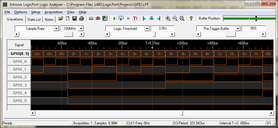
GPIO
The Jasmine Board has 7 GPIO pins, 6 GPIO pins can be used for debugging with a logic analyzer, 2 GPIO pins are available if UART is used but caution should be taken with their use, see Pins.
To use J4 (GPIO_2 through GPIO_5) turn “ON” all four SW4 switches and turn “OFF” switches 1 through 4 on SW2 to prevent the MAX3232 chip from interfering with GPIO. If using J4 set the GPIO_MOD register to 7 otherwise J4 will return spurious signals.
You can use GPIO for debugging without JTAG or interfacing with external devices.
Initialization
SETREG(GPIO_DIR, BIT0 | BIT1 | BIT3 | BIT4 | BIT6); // Enable GPIO 0,1,3,4,6
Communication
Read GPIO
UINT32 temp = GETREG(GPIO_REG)
Set GPIO
SETREG(GPIO_REG, 0x3) // Set Pins 0 and 1 to HIGH
Pins
| Name | Pin |
|---|---|
| GPIO_0 | JP2 - Center Pin on Factory Mode jumper * Remove the jumper before powering on the board or you may damage the circuit board if this pin is enabled. |
| GPIO_1 | JP3 - Center Pin on Boot ROM * Must be shorted before powering on the board |
| GPIO_2 | J4 - Turn on SW4 switch to use * Shared with UART, you cannot use both simultaneously |
| GPIO_3 | J4 - Turn on SW4 switch to use * Shared with UART, you cannot use both simultaneously |
| GPIO_4 | J4 - Turn on SW4 switch to use * Shared with UART, you cannot use both simultaneously |
| GPIO_5 | J4 - Turn on SW4 switch to use * Shared with UART, you cannot use both simultaneously |
| GPIO_6 | D4 - LED connected via SW2 #5 |
Example
The example code below endlessly outputs the value 0x0 through 0x3F to the GPIO pins which can read using a Logic Analyzer.
SETREG(GPIO_MOD, 7);                // Enable use of GPIO_2 through GPIO_5

SETREG(GPIO_DIR, BIT0 | BIT1 | BIT2 | BIT3 | BIT4 | BIT5 | BIT6);
                                    // Enable GPIO_0 through GPIO_6
                                    // Only 0-5 are used in this example
                                    // GPIO_6 is the LED, if we replace 0x40 with 0x80
                                    // the LED with blink when bit 6 is set high or low
while(1){ // Endless Loop
    for(UINT32 i = 0; i < 0x40; i++){
        delay(1000);	     // Let GPIO Settle
        SETREG(GPIO_REG, i); // Send value 0x0 - 0x3F to GPIO
    }
}
3. Coding (toc)
ftl_tutorial
If you’re using ftl_tutorial as your skeleton remember to comment out format() in ftl_open() or it will erase the NAND on every boot.
if (check_format_mark() == FALSE)
{
	// When ftl_open() is called for the first time (i.e. the SSD is powered up the first time)
	// format()
}
4. Debugging (toc)
Serial Debugging
The Jasmine board includes a serial port for debugging, you can enable serial debugging by setting OPTION_UART_DEBUG to 1 in Jasmine.h. If your computer doesn’t have a serial port you can purchase a USB to serial adapter, be warned that some USB serial adapters may have buggy drivers which blue screen when data is rapidly sent from the Jasmine.
To view serial output you can use any serial terminal, I’m using PuTTY, set the Connection type to Serial and change Serial Line to your COM port, and set the Speed to 115200. I suggest saving the session so you can quickly reload these settings.
Read/Write Debugging
When debugging ftl_read & ftl_write routines I recommend using a USB SATA adatper. If a bug is present in your code while using the hosts SATA controller a deadlock may occur which will take minutes to resolve. Using a USB SATA adapter allows you to unplug the adapter and return your system to normal use should a deadlock occur.
5. Hot Swapping (toc)
If your SATA controller supports hot swapping you may wish to hot swap rather than rebooting on every firmware load, the ICH10 controller (previous revisions may work to) combined with the latest Rapid Storage Technology driver from Intel have proved the most consistent for me. To hot swap make sure your controller is in AHCI (or RAID) mode, then go to Device Manager and right click on Scan for Hardware Changes. When programming I perform the following actions:
- While the board is in Factory Mode, load the firmware.
- Turn off the board and set the jumper to normal mode.
- Scan for hardware changes.
- Turn the board on.
- Scan for hardware changes.
Whether switching to or from Factory Mode its best to scan for hardware changes before powering on the board otherwise the SATA interface will become locked for a minute while the SATA controller waits for devices to timeout/settle.